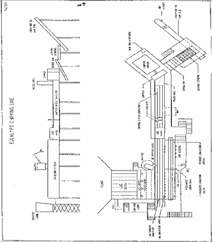
EUCALYPT WOOD LINE
This product is not available at the moment. Please contact our customer service for more info.
-
Print this page
- Product ID: VAK10707
- Name: EUCALYPT WOOD LINE
EUCALYPT WOOD LINE
Overview
The Eucalypt wood line was designed by HA Simons and installed in 1985. It is used to chip mixed eucalyptus species regrown logs up to 700mm diameter and has a 2860 mm Carthage horizontal feed chipper (1976) with six sets of blades driven by a 1,750 HP induction motor. The capacity is 200 tonnes per hour. The woodline is operated by two man crew on twelve hour shifts on a continuous roster.
The process flow is, in summary:
Logs are placed on the receiving deck where they are conveyed by chains to an unscrambler drum which breaks down large bundles of logs into small groups or single logs. There is a hydraulic grapple for removal and straightening of logs on the receiving deck and unscrambler.
The logs then pass over the unscrambler drum and fall into a chain conveyor to the log wash sprays. After the sprays, a second and third chain conveyor carries the logs to the Eucalypt chipper.
At the front of the log unscrambler drum there is a set of kicker arms to allow an oversize or bent log to be unloaded. Rejected logs are conveyed to an oversize log bunker or, if bent, cut using a deck mounted hydraulic chainsaw to allow them to be processed and returned to the line for chipping.
Following the chipper, there is a surge conveyor, slivers screen, 234m long conveyor to the chip storage pile where they are distributed by a flinger conveyor.
The eucalypt woodline is expected to cease operation in early 2008.
In some more detail:
Log Receiving Deck
The log receiving deck is 14 metres wide with 2 metre high sidewalls.
The front of the log receiving deck is sloped so that logs will roll down onto the chains when the logs on the receiving deck are moved along. There are twelve linked chains with cleats.
These chains are driven independently by two Hagglunds hydraulic drive motors.
Eucalypt Grapple
The grapple is located on the north side of the log receiving deck and is used to straighten logs, assist with the removal of jammed logs in conveyors, remove oversize logs from conveyors, log receiving deck or log unscrambler drum and place logs in the oversize log bunker.
The 15 tonne Nicholson pedestal mounted log grapple is operated from an enclosed cabin on a rotating platform that can be rotated or held in any position within a 280 degree radius.
The control is electric over hydraulic.
Feeder Bars
There are 4 feeder bars operated individually by hydraulic cylinders to control and regulate the feed of logs onto the unscrambler drum.
Unscrambler Drum
The log unscrambler drum transfers logs from the log receiving deck pocket to the log shower conveyor or to the oversize log conveyor.
The drum is driven by a Hagglunds hydraulic drive, with its speed under operator control.
Log Unloader Arms
The hydraulically driven log unloader arms are used to transfer oversize logs from the log unscrambler drum to the oversize log conveyor south.
Refuse Deck (Walking Floor)
The refuse deck (walking floor) is located underneath the log unscrambler drum and is used to transfer waste bark, dirt and sticks from the log receiving deck and the log unscrambler drum onto the conveyor to refuse pile.
The refuse deck walking floor is hydraulically operated and is split into four sections.
Oversize Log Conveyor South
The oversize log conveyor south is used to transfer oversize logs to the deck mounted chainsaw and to the oversize log conveyor north.
The oversize log conveyor south is a variable speed reversing chain conveyor driven by hydraulic motors at both the head and tail sprockets.
Oversize Log Conveyor North
The oversize log conveyor north is used to transfer oversize logs from the deck-mounted chainsaw and the oversize log conveyor south.
The oversize log conveyor north is a variable speed reversing chain conveyor driven by hydraulic motors at both the head and tail sprockets.
Deck Mounted Chainsaw and Log-Jack
The deck mounted chainsaw and log jack are located between the north and south oversize log conveyors. The log jack is used to lift the logs up off the conveyor chains so that the oversize or badly bent log can be cut with the deck mounted chainsaw.
The deck mounted chainsaw is hydraulically driven and the log jack is also hydraulically operated.
Log Kickers
The four hydraulically operated log kicker bars are used to push logs from the north oversize log conveyor onto the oversize log by-pass gate or into the conveyor to the log shower.
Oversize Log By-Pass Gate
The hydraulically operated oversize log by-pass gate is used to transfer logs from the North oversize log conveyor into the oversize log bunker.
Conveyor to Log Shower
The conveyor-to-log-shower transfers logs from the unscrambler drum to the log shower. It is a variable speed reversing chain conveyor driven by hydraulic motors at both the head and tail sprockets.
Log Shower
The log shower washes mud, dirt and fine bark from the logs. This flows through the holes in the bottom of the log wash to a chute back to the bark plant (see ancillaries).
The very long pieces of bark fall onto a refuse conveyor. (see Ancillaries)
Chipper Infeed Conveyor
The chipper infeed conveyor transfers logs from the log shower to the eucalypt chipper. It is a variable speed reversing chain conveyor driven by hydraulic motors at both the head and tail sprockets.
Press Roll
The press roll is used to pull logs out of the chipper spout that become stuck or occasionally to assist the feeding of bent logs or small groups of logs into the chipper.
The press roll is driven by a reversible hydraulic motor and is lifted and lowered by a hydraulic cylinder.
Chipper
2860mm horizontal feed Carthage chipper with six sets of blades, (two blades to a set), set at a 32 degree angle has a capacity of 195 tonnes per hour. Logs of up to 12 metre length and up to 700mm diameter or groups of logs up to 700mm are fed to the chipper disc and anvil (bed knife). The chips produced are 4-8 mm thick and 19mm long.
The chips fall into a surge bin underneath the chipper.
The chipper speed is 295 rpm, driven by a 3.3kV 3 phase 1,750HP induction motor.
There is a spare chipper disk with 12 knife sets.
Chipper Surge Conveyor
The first conveyor in the chip handling system is the chipper surge conveyor. It is located at the north end of the eucalypt wood line. This conveyor is an upside-down flight conveyor.
This conveyor evens out the surges of chips produced by the chipper. The surge conveyor is a trough about 1 metre high with straight sides open at the top. The chain and flight bars (made of square steel tube) carry the chips up the conveyor to the discharge. The drive is by electric motor, V-belts and gearbox.
Slivers Screen
The slivers screen follows the surge conveyor and is a Rader disk screen with eight, 6 foot shaft rolls with plate blades overlapping at different thicknesses to allow accepted chips to fall through the screens. Reject chips, long slivers and bark are carried to the back where they fall onto the slivers conveyor. The slivers screen has two electric drives.
Conveyor to Chip Pile (Note – may not be available for sale – still to be finalised)
The conveyor to chip pile takes chips from the slivers screens to the outside chip storage areas. It is a rubber conveyor belt about 234 meters long and about 1 meter wide with counterweight tensioning and head pulley electric drive through V-belts and gearbox.
A weightometer is positioned about halfway up the incline of the conveyor to chip piles.
Chip Slinger (Note – may not be available for sale – still to be finalised)
The slinger belt is 3.7 metres long and 710mm wide, travelling at 20 metres per second and throwing a jet of chips 10 – 20 metres in the desired direction. It can be rotated 300 degrees and adjusted up or down. The chip slinger is driven by an electric motor through V-belts.
A bypass gate is located about halfway up the transfer chute
PINE WOODLINE
Overview
The pine woodline was designed by HA Simons and installed in 1983. It is used to chip plantation pinus radiata of up to 700mm diameter. It has a Carthage 2845mm drop feed chipper with 12 sets of blades operating at 360rpm, flat-belt driven from a 1119kW, 423rpm 3.3kV motor, for a capacity of 250 - 300 tonnes per hour.
The line is operated by two men on twelve hour shifts on a continuous roster.
The process flow is, in summary:
Logs are placed on a receiving deck and moved along by chains fall to the bottom of the log sorting deck where bundles are separated and individual logs are transferred to a conveyor feeding the barking drum. There is a hydraulic grapple used to remove log jams from the log receiving deck and log sorting deck.
Debarked logs discharge from the barking drum down a chute onto a short five chain discharge conveyor.
From this conveyor the logs pass over a three sets of speed up rollers and sorting rollers whose function is to sort them into a single file or small groups for delivery to the chipper infeed conveyor and then into the chipper.
As the logs pass over the third set of speed up rollers the logs are washed clean of any residual dirt and loose bark with recycled water from the barkplant.
An oversize log gate is provided between the second and third set of speed up rollers. Its function is to control the bunching of logs and to sort out the larger and oversized logs.
After the third set of speed up rollers there is a cut-off saw to cut a badly bent log or a big log in half so it will not overload the chipper. Between the cut-off saw and the chipper there is a metal detector.
From the chipper the chips fall into a surge bin and are then transferred by the surge bin conveyor onto a 250 metre belt conveyor to the chip storage pile where they are distributed by a flinger conveyor.
The pine wood line is expected to cease operation in early 2008.
In some more detail:
Log Receiving Deck
The log receiving deck is nine metres wide and ten metres long with sidewalls.
There are eight linked chains across the deck and speed is variable up to 4.5 metres per minute.
Pine Line Grapple
The hydraulic grapple with extension boom fitted can lift 1.3 tonnes at its maximum reach of 7.5 metres, or 2.5 tonnes at 5.0 metres and can slew 360 degrees.
It is used to remove log jams from the log receiving deck and log sorting deck.
Log Sorting Deck
The log sorting deck separates bundles of logs delivered from the log receiving deck. It has a flat bottom and is fifteen metres long including the incline and the width is nine metres.
There are twelve linked chains recessed into deck and fitted with flight bars spaced one metre apart to allow two or three logs to fit between them.
There are also twelve flop gates at the west end of the unscrambler these flop gates allow the flight bars to pass under the flop gates but not allow logs to roll under the flop gates.
The speed of the log sorting deck (unscrambler) is variable.
Barking Drum Infeed Conveyor
A chain conveyor transfers logs from the sorting deck to the barking drum.
Barking Drum
The barking drum is Waplans NRE-420 supported on water bearings and electrically driven through a gearbox and ring-gear.
There is a spare bearing ring available.
Barker Discharge Conveyor
The barker discharge conveyor is a chain conveyor (5 chains with cleats) used to transfer logs from the barking drum to the speed up rollers. It is driven by an electric motor through a gearbox and chain at 38m/per/min.
Speed Up Rollers
The speed-up rollers are used to sort and transfer logs from the barker discharge to the chipper infeed conveyor. These speed-up rollers are in three sections with each section driven by an electric motor through a gear box and chain drive.
The rollers are spiked and spiralled to ensure that logs pass through the log shower in single file or in small bundles.
Oversize Log Gate
There is an adjustable oversize log gate positioned on the north end of No. 2 section to stop surges of logs from jamming in the narrower Section No. 3 and to separate larger diameter logs.
Log Shower
The log shower is located after the speed up rollers and washes any residual dirt or bark from the logs using recycled water.
Cut-Off Saw
The cut-off saw is positioned after the speed up rollers and is used to cut a badly bent log or to cut a larger log in half so it does not overload the chipper. The saw chain is electrically driven, while the saw bar and log jack are hydraulically operated.
Chipper Infeed Conveyor
The chipper infeed conveyor is used to transfer logs from the speed up rollers to the chipper.
It is driven by an electric motor through v-belts and gearbox. This also drives the chipper chute thrower roller which is spiked and pulls the logs into the chipper chute and helps to free up jams. This drive can be reversed and travels at 76 m/min.
The infeed conveyor is a rubber belt 720mm wide, tensioned by counterweight.
Crane
The crane is mounted on a steel pole alongside the speed-up rollers and is used to remove logs from the barker discharge conveyor or the speed up rollers.
It has a safe working load of two tonnes and is electrically driven by two electric motors.
Winch
There is an electrically driven winch located above the exit of the chipper infeed conveyor to get log jams out of the chipper infeed conveyor chute.
Pine Chipper
The pine chipper is a Carthage 2845mm drop feed unit with twelve blades set at an angle of 35 degrees operating at 360 rpm, driven by a 1,119 kW 3.3kV electric motor with a flywheel pulley which in turn flat belt-drives a flywheel pulley on the chipper.
5.5 metre logs of up to 700mm diameter are fed down a chute to the chipper and the chips are discharged via card-breakers to a conveyor underneath the chipper.
The chipper is set to produce chips 19mm long and the geometry of the knife slots and card-breakers is designed to produce chips in the thickness range 58mm.
Surge Bin & Chipper Discharge Conveyor
The chipper discharge conveyor transfers the chips from the chipper to the conveyor to the outside storage pile.
The chips fall from the chipper into a 20 m3 surge bin. At the head end of this bin there is an adjustable gate set to achieve a continuous flow of chips. The discharge conveyor has three linked chains which pull the chips along the conveyor. This conveyor has a flat bottom with the return chain travelling underneath. This conveyor travels at 18m/min.
Chip Storage Pile Conveyor (Note – may not be available for sale – still to be finalised)
The belt conveyor to the outside chip storage pile transfers chips from the chipper discharge conveyor to the outside chip storage pile. It is a rubber belt conveyor about 250 metres long by one metre wide with a tensioning counterweight at the discharge end. There is a weightometer is located half way up the incline of the conveyor.
The drive is electric motor through v-belts to a gearbox shaft-mounted on head pulley.
Slinger (Note – may not be available for sale – still to be finalised)
The chip slinger is a short rubber belt conveyor which travels at a speed of 20 metres per min and throws a jet of chips 10 to 20 metres in any desired direction.
The slinger belt is 3.7 metres long by 700mm wide and can be rotated 300 degrees and tilted between 20 degrees down to 50 degrees up. The chip slinger has an electric v-belt drive on the tail pulley.
There is a bypass gate on the transfer chute from the storage pile conveyor
ANCILLIARY PLANT
The function of the ancillary plant is to transfer waste bark and debris from the two wood lines to the waste bark storage area and to separate and recycle water to the log washes on the two lines
The transfer drains carrying the bark, dirt and sticks from the two wood lines (not including the pine barking drum) flow over inclined screens. The bark, sticks, fines fall onto the chain drag conveyor discharging onto a rubber belt conveyor to a storage pile which also receives slivers, dirt, fines and bark from the eucalypt line.
The water from the screens is pumped into a grit collector where fine dirt and mud settles to the floor and is transferred by a slow moving drag chain into a hopper for disposal.
Excess water from the grit collector flows to a head tank and is then pumped back to the log washes on both wood lines.
In some more detail:
Conveyor to Refuse Pile
This conveyor runs from the eucalypt wood line underneath the pine wood line to the waste bark storage area, transferring waste bark, sticks and fine dirt from the receiving, unscrambling and refuse deck area of the eucalypt line as well as slivers from the eucalypt slivers screen and solids from the inclined screens to a refuse pile. It has a 1 metre wide rubber belt with counterweight tensioning, with an electric motor driving the head pulley though V-belts and a gearbox.
Slivers Conveyor
The slivers conveyor transfers waste bark the eucalypt slivers screen and the bark plant inclined screens to the conveyor to refuse pile. This conveyor is a 600mm rubber belt driven at the head shaft by an electric motor, v-belts and gearbox.
Bark Plant
Primary Screens
The two primary screens are used to separate the water from the waste bark.
These stainless steel fine-hole screens are 1.8 metre x 1.5 metre. Water, dirt and waste bark that is washed from the logs flows from the pine and eucalypt wood lines over these screens.
The water is separated and the waste bark and dirt slides onto a scraper chain conveyor. This transfers the waste to a belt conveyor, the ‘refuse conveyor from bark plant’. Both conveyors are driven from their head shafts by electric motor though v-belts and a gearbox. The belt conveyor is 600mm wide and has a tensioning weight at the tail drum.
Grit Collector
The Grit Collector is used to separate the mud and dirt from the water from the screens by gravity settling. It is made of concrete and has a flat bottom with a slow moving linked drag chain conveyor removing solids. This drag chain is driven by an electric motor from head shaft.
Log Wash Pumps
The two log wash pumps take recycled water from the grit collector to the log showers on both wood lines. These two pumps have v-belt drives.
Other
There are also expected to be under-pile chip reclaim feeders and conveyors together with chip screening systems and a pneumatic chip conveying system available for sale